Production of components for ripple control transmitters to hv levels
The Ripple Control Division produces a control and power system for ripple control transmitters with 250kVA typical power output, intended for transmitters to hv levels (up to 35kV level).
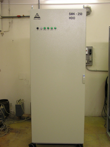
Information on the SMK 250 innovated technology for ripple control transmitters to hv levels
By the end of 2003, the technology of the SMK 250 case experienced technical modifications logically implied from deploying the new VLK 10 control and regulation system, which supersedes the VLK 04, still used for these ripple control transmitters. In this context, it is necessary to say the new VLK 10 system is based on the basic control and regulation algorithms for ripple control transmitters, already used in the VLK 04 systems, but in this case, an advanced hardware is used allowing a different design solution and more developed way of communication with transmitters.
As regards of a technical specification, the new SMK 250 case is identical with the older technology, namely with regard to the following primary values :
| Input supply from the 50Hz home consumption transformer: | 3 × 400V / (±10%) |
| 50Hz phase input current: | app. 150A |
| Converter operating frequency: | 170–770Hz |
| Apparent output power: | max. 250kVA |
| Time carrying capacity – typical long-term value: | 10% |
The size of the new case decreased with regard to width: (h × w × d) 2000mm × 800mm × 600mm; also the 100mm base is assumed for an application as with previous solutions for attaching the C1 case, which is to stay in the same fashion as with previous implemented ripple control transmitters.
The most substantive modification in the converter’s power component is the substitution of fuses and a power deon with an up-to-date fuse switch isolator, which fulfills, together with semiconductor fuses, the function of both previous components. This solution, together with a revised control component, allows assembling the whole technology only onto the back installation panel of the case and simplifies an access to and lucidity of components used. In the upper part of the case, the power component is placed (without intermediate DC circuit), in its lower part, the VLK 10 system modules, transmitter supporting circuits (pulse source, sensing, communication, and switching circuits), terminal block for the whole SMK 250 technology, and a fuse switch isolator are placed. An intermediate DC circuit (power capacitors with an intermediate-circuit chocking coil) is placed on the bottom of the case in front of an assembly panel, under connecting terminal blocks, so the circuit will allow simple connecting power as well as week-current cables. On case doors, in the upper part, the control and signaling elements are placed in a line. On the back of the door, the MODEM is placed.
Remote parameterization and diagnostic integrated functions belong to the VLK 10 new modular system's main advantages (in comparison with the original solution with the VLK 04). This leads to a diagnostic time substantive shortening and possible equipment malfunction avoiding or to the external disruptive influence of operation identifying (e.g. by the influence of strong cross talk signals between transmitters operated, in the case of synchronization failures, etc.), particularly where any substation stable operating personal is not present.
By means of four principal module types, it is possible to compose a transmitter control system in required configuration – up to four coupling elements for the ripple control transmitter to hv levels (provided the stationary source used will have a sufficient power). Individual modules have the approx. size of 100 × 100 × 100 mm and they are fitted on DIN strip. A common supply is ensured from a pulse source. Connecting the modules to the internal RS 485 net ensures communication. The whole system is designed as open, which allows other modules subsequently to connect.
CM central module – contains a fully valuable local automation, communicates with surrounding environment (e.g. with a central automation, the same way as original transmitters), controls the internal RD 485 bus, and coordinates the operation of all subordinated modules installed in a given particular system. It is fitted with RS 422 / RS 232 serial channels, to which it is possible simultaneously to connect e.g. two computers serving as terminals, that mediate monitoring of module operation for an operator, an archive browsing, transmitter testing, limit adjusting for the C1 automatic tuning, etc.
SM synchronization module – allows synchronizing the transmitter with other transmitters operated on the same frequency, contains the complete GPS satellite receiver and circuits for the transmitter's operating frequency phase adjusting in the range of 0 – 360 angle degrees by approx. 1.4-gradus steps. Based on the IPK signal from the CM, the sync module generates a pilot frequency directed to the RM modules' inputs.
RM control module – based on the pilot frequency, it generates triggering pulses for one three-phase stationary frequency converter, monitors its critical parameters and, in the case of their leaving an adjusted range, it will switch off the converter or give input to subordinated X modules for retuning C1 batteries.
XM coupling module – monitors and stores to an archive the U2 voltage and I2 current values of one linkage per every transmitter keying, implements the optimal adjusting of C1 batteries' operating values (according to inputs from the RM), measures the current network frequency, monitors and stores to an archive external input conditions for the coupling element's preparation, and switches off the transmitter in the case of exceeding the I2 adjusted maximum (resulting from the operating frequency used and the C2 coupling capacitors' type used), or if any condition for the transmitter's PREPARATION will be lost.
For the most common ripple control transmitter to 22kV level with two linkages, the VLK 10 system is fitted with the following five modules – CM, SM, RM, XM 1, and XM 2. To the transmitter recommend we to have one set of parts for the first fitting (spare modules, supporting circuits, fuses etc.).
In this time is the new technology of the ripple control transmitter SMK 250 in operation in Most – sever, Most – jih, Havraň, Rakovník, Náchod – Babí, Albrechtice, Ropice, Nošovice, Jihlava – Bedřichov, Žďár nad Sázavou and Havlíčkův Brod substations.
